Friday, 18 July 2014

Resistor Manufacture

This my second post on Resistor component
if you want to know what is  a resistor you can got o my previous post Resistor
Now ,,,,How a resistor is manufactured???
Almost all resistors are manufactured by machine. The ceramic core is molded and pressed by machine. Individual cores are made to fit different sized resistors. The cores are then "wire wound" using another machine that wraps the resistor material around the core. The lead ends, which include both the metal wire and a cap end that is shaped like a bottle cap, are then pressed onto the core. The cores are painted with typical paint or a baked on finish.
resistor manufacturing process begins with the selection of suitable material
Materials:
there are numerous types of materials used in resistor manufacturing
some of them are
1.CARBON
2.FILMS OF CARBON,METALS,METAL OXIDES
3.WIRE-WOUNDS OF METALS
etc..;
Carbon resistors:
Image
A carbon resistor is the most common type. This is made by wrapping a carbon track around a ceramic core. The carbon track is wound around the ceramic core by a machine or etched into the core with a laser device. Two copper metal leads are then inserted in the ends of the resistor, so the ends of the track are touching the leads. The resistor is then painted to seal the core.
The Carbon Composite Resistor is a low to medium type power resistor which has a low inductance making them ideal for high frequency applications but they can also suffer from noise and stability when hot. Carbon composite resistors are generally prefixed with a “CR” notation (eg, CR10kΩ ) and are available in E6 ( ± 20% tolerance (accuracy) ), E12 ( ± 10% tolerance) and E24 ( ± 5% tolerance) packages with power ratings from 0.125 or 1/4 of a Watt up to 5 Watts.
Carbon composite resistor types are very cheap to make and are therefore commonly used in electrical circuits. However, due to their manufacturing process carbon type resistors have very large tolerances so for more precision and high value resistances, film type resistors are used instead.
FILM TYPE RESISTORS:
Image
The generic term “Film Resistor” consist of Metal FilmCarbon Film and Metal Oxide Film resistor types, which are generally made by depositing pure metals, such as nickel, or an oxide film, such as tin-oxide, onto an insulating ceramic rod or substrate.

The resistive value of the resistor is controlled by increasing the desired thickness of the deposited film giving them the names of either “thick-film resistors” or “thin-film resistors”. Once deposited, a laser is used to cut a high precision spiral helix groove type pattern into this film. The cutting of the film has the effect of increasing the conductive or resistive path, a bit like taking a long length of straight wire and forming it into a coil.
This method of manufacture allows for much closer tolerance resistors (1% or less) as compared to the simpler carbon composition types. The tolerance of a resistor is the difference between the preferred value (i.e, 100 ohms) and its actual manufactured value i.e, 103.6 ohms, and is expressed as a percentage, for example 5%, 10% etc, and in our example the actual tolerance is 3.6%. Film type resistors also achieve a much higher maximum ohmic value compared to other types and values in excess of 10MΩ (10 Million Ω´s) are available.
Metal Film Resistors have much better temperature stability than their carbon equivalents, lower noise and are generally better for high frequency or radio frequency applications. Metal Oxide Resistors have better high surge current capability with a much higher temperature rating than the equivalent metal film resistors.
Another type of film resistor commonly known as a Thick Film Resistor is manufactured by depositing a much thicker conductive paste of CERamic and METal, called Cermet, onto an alumina ceramic substrate. Cermet resistors have similar properties to metal film resistors and are generally used for making small surface mount chip type resistors, multi-resistor networks in one package for pcb’s and high frequency resistors. They have good temperature stability, low noise, and good voltage ratings but low surge current properties.
Metal Film Resistors are prefixed with a “MFR” notation (eg, MFR100kΩ) and a CF for Carbon Film types. Metal film resistors are available in E24 (±5% & ±2% tolerances), E96 (±1% tolerance) and E192(±0.5%, ±0.25% & ±0.1% tolerances) packages with power ratings of 0.05 (1/20th) of a Watt up to 1/2 Watt. Generally speaking Film resistors are precision low power components.
WIRE-WOUND TYPE OF RESISTORS:
Image
Another type of resistor, called a Wirewound Resistor, is made by winding a thin metal alloy wire (Nichrome) or similar wire onto an insulating ceramic former in the form of a spiral helix similar to the film resistor above. These types of resistor are generally only available in very low ohmic high precision values (from 0.01 to 100kΩ) due to the gauge of the wire and number of turns possible on the former making them ideal for use in measuring circuits and Whetstone bridge type applications.
They are also able to handle much higher electrical currents than other resistors of the same ohmic value with power ratings in excess of 300 Watts. These high power resistors are moulded or pressed into an aluminium heat sink body with fins attached to increase their overall surface area to promote heat loss and cooling.
These special types of resistor are called “Chassis Mounted Resistors” because they are designed to be physically mounted onto heatsinks or metal plates to further dissipate the generated heat. The mounting of the resistor onto a heatsink increases their current carrying capabilities even further.

Another type of wirewound resistor is the Power Wirewound Resistor. These are high temperature, high power non-inductive resistor types generally coated with a vitreous or glass epoxy enamel for use in resistance banks or DC motor/servo control and dynamic braking applications. They can even be used as low wattage space or cabinet heaters.
The non-inductive resistance wire is wound around a ceramic or porcelain tube covered with mica to prevent the alloy wires from moving when hot. Wirewound resistors are available in a variety of resistance and power ratings with one main use of power wirewound resistor is in the electrical heating elements of an electric fire which converts the electrical current flowing through it into heat with each element dissipating up to 1000 Watts, (1kW) of energy.
Because the wire is wound into a coil inside the resistors body, it acts like an inductor causing them to have inductance as well as resistance and this affects the way the resistor behaves in AC circuits by producing a phase shift at high frequencies especially in the larger size resistors. The length of the actual resistance path in the resistor and the leads contributes inductance in series with the “apparent” DC resistance resulting in an overall impedance path of Z Ohms.
Impedance ( Z ) is the combined effect of resistance ( R ) and inductance ( X ), measured in ohms and for a series AC circuit is given as, Z 2 = R 2 + X 2.
When used in AC circuits this inductance value changes with frequency (inductive reactance,XL = 2πƒL) and therefore, the overall value of the resistor changes. Inductive reactance increases with frequency but is zero at DC (zero frequency). Then, wirewound resistors must not be designed or used in AC or amplifier type circuits where the frequency across the resistor changes. However, special non-inductive wire-wound resistors are also available.
                                                                                                                                                                                                           
By this manufacturing process of resistor ends
In the  next we will discuss about about SMD resistors

Resistor

Let us start our Journey of electronics with  simple component called "Resistor"
Resistor:
Resistor is simple component which resist the flow of current(i.e., electrons) through it
due to its resisting capability , it is called as Resistor
SYMBOL
In Electronics World, the symbol used to represent  a Resistor is
Image
OK, if you are new to electronics then u have a doubt .."why this symbol is like this , why it not like a square or a circle".
Let me clear it , Generally in any conducting material  flow of electrons takes place without any  resistance, if we consider a straight line   to be a conductor in which the electrons can flow  easily with out any resistance......whereas in a resistor  speed of electronics get decreased .....instead of representing a complete internal structure  of a resistor in a schematic  we can use a zigzag symbol which serves as best symbol for a resistor.
UNIT
Now we are clear with the symbol...now we can move on to its unit representation
Generally ,in world every material is represented by its units like
liquid.......in Litres
masses......in Kilo grams etc..,
In the same way resistor's resistance has its own unit called "ohms" it is represented as 'Ω'.
HISTORY
Let's get into the history of resistor.....,
A German Physicist and mathematician named Georg Simon Ohm is the one who led to the discovery of resistance.
2GEORG-OHM
he conducted many experiments on Electrical circuits and came to a conclusion  that...
"For any particular conductor at a constant temperature, the current that flows through it is directly proportional to the potential difference applied across it."
VαI
V→Voltage
I→current
we can re-write the above as→    V=(some constant)xI
later this constant is termed as the resistance of the circuit by simon ohm
that is  "   V=IR    "
   R→resistance
this called as Ohm's law
a simple circuit representing ohm's law    is as follows
  res-600x368
where is 'R' is the Resistance offered by the conductor.
Till now we have seen the what is a Resistor...
In next post i will explain how a resistor is manufactured ....till then good bye

DIODE

What is a DIODE ?
Name  indicates DI-ODE
which means DI-->TWO        and         -ODE  refers to -->ELECTRODES
Simply it is a two terminal(Electrode) component
--->But there is a lot of difference between diode and a Photo Diode
Working :Diode allows the flow of current only in one direction(called as Forward direction) i.e ., from (+)ve to (-)ve and
this is possible by the diode, if and only if it offers less resistance in Forward Direction and high resistance in reverse direction
                                                                     diode
SYMBOL :
                             download
     The Symbol Simply Indicates the Forward Direction of the diode
and on the original component a white strip of paint indicates the (-)ve Terminal of the Diode
Applications: Due to its characteristics Diode has many applications in our electronic world
The Unidirectional behavior of diode  is called as Rectification and is used   in converting Alternating current to direct current
--->Diode is also called as "Rectifier"

Power Conversion

One significant application of diodes is to convert AC power to DC power. A single diode or four diodes can be used to transform 110 V house-hold power to DC by forming a half-way (single diodes) or a full-wave (four diodes) rectifier. A diode does this by allowing only half of the AC wave form to travel through it. When this voltage pulse is used to charge a capacitor, the output voltage appears to be a steady DC voltage with a small voltage ripple. Using a full wave rectifier makes this process even more efficient by routing the AC pulses so both the positive and negative haves of the input sine wave are seen as only positive pulses, effectively doubling the frequency of the input pulses to the capacitor which help keep it charged and deliver a more stable voltage.
Diodes and capacitors can also be used to create a number of types of voltage multipliers to take a small AC voltage and multiply it to create very high voltage outputs. Both AC and DC outputs are possible using the right configuration of capacitors and diodes.

Demodulation of Signals

The most common use for diodes is to remove the negative component of an AC signal so it can be worked with easier with electronics. Since the negative portion of an AC waveform is usually identical to the positive half, very little information is effectively lost in this process. Signal demodulation is commonly used in radios as part of the filtering system to help extract the radio signal from the carrier wave.

Over-Voltage Protections

Diodes also function well as protection devices for sensitive electronic components. When used as voltage protection devices, the diodes are non-conducting under normal operating conditions but immediately short any high voltage spike to ground where it cannot harm an integrated circuit. Specialized diodes called transient voltage suppressors are designed specifically for over-voltage protection and can handle very large power spikes for short time periods, typical characteristics of a voltage spike or electric shock, which would normally damage components and shorten the life of an electronic product.

Current Steering

The basic application of diodes is to steer current and make sure it only flows in the proper direction. One area where the current steering capability of diodes is used to good effect is in switching from power from a power supply to running from a battery. When a device is plugged in and charging, for example a cell phone or uninterrupted power supply, the device should be drawing power only from the external power supply and not the battery and while the device is plugged in the battery should be drawing power and recharging. As soon as the power source is removed, the battery should power the device so no interruption in noticed by the user.

Resistor color code


Day to day advancement in technologies is creating better life
one of the wonder of advanced technology is SMD's→surface mount devices
in smd's the size of  device is very small compared to its original one
                   SMD→ 100ksmdresis Resistors_color_code ←NORMAL
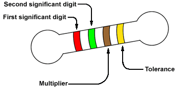
IN NORMAL RESISTORS we use color coding for identification of its resistance
Resistor
resistorcolorcode
click on this link to get resistor calculator 

but in smd's

How to calculate the value of an SMD resistor

Most chip resistors are marked with a 3-digit or 4-digit code
NOTE:
  • an SMD resistor with a marking of 0, 00, 000 or 0000 is a jumper (a zero-ohm link).

The 3-digit code

Standard-tolerance SMD resistors are marked with a simple 3-digit code. The first two numbers will indicate the significant digits, and the third will be the multiplier, telling you the power of ten to which the two significant digits must be multiplied (or how many zeros to add). Resistances of less than 10 ohms do not have a multiplier, the letter 'R' is used instead to indicate the position of the decimal point.
3-digit code examples:
220 = 22 × 100 (1) = 22Ω (not 220Ω!)
471 = 47 × 101 (10) = 470Ω
102 = 10 × 102 (100) = 1000Ω or 1kΩ
3R3 = 3.3Ω

The 4-digit code

The 4-digit code is used for marking precision surface mount resistors. It's similar to the previous system, the only difference is the number of significant digits: the first three numbers will tell us the significant digits, and the fourth will be the multiplier, indicating the power of ten to which the three significant digits must be multiplied (or how many zeros to add). Resistances of less than 100 ohms are marked with the help of the letter 'R', indicating the position of the decimal point.
4-digit code examples:
4700 = 470 × 100 (1) = 470Ω (not 4700Ω!)
2001 = 200 × 101 (10) = 2000Ω or 2kΩ
1002 = 100 × 102 (100) = 10000Ω or 10kΩ
15R0 = 15.0Ω
click on this link for smd calcualtor
This the end of the post

Battery Charge Indicator

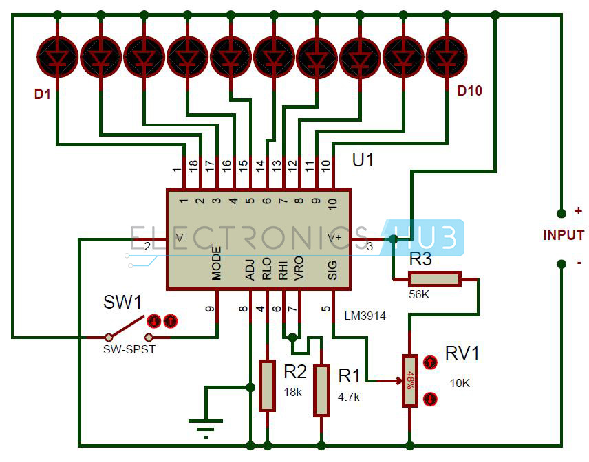
Battery Level Indicator Circuit Diagram
Circuit Components:
  • Lm3914 IC
  • LED’s -10
  • SPST switch
  • Resistors -18k,4.7k, 56k
  • Potentiometer – 10k
  • 12V battery
  • Connecting wires

Battery Charge Indicator Circuit Design:

In this circuit LED’s (D1-D10) displays the capacity of the battery in either dot mode or display mode. This mode is selected by the external switch sw1 which is connected to 9th pin of IC. 6th and 7th pins of IC are connected to the ground through a resistor. This resistor controls the brightness of LED’s. Here resistor R3 and POT RV1 forms potential divider circuit. Here pot RV1 is used for calibration. There is no need of any external power supply to this circuit.
The circuit is designed to monitor 10V to 15V DC. The circuit will work even if the battery voltage is 3V. The operating voltage of this IC is 3v to 25v DC. Lm3914 drives led’s, LCDs and vacuum fluorescents. The IC contains adjustable reference and accurate 10-steps divider. This IC can also acts as sequencer.
Lm3914 Features:
  • Internal voltage reference from 1.2 to 12v DC.
  • Programmable output current 2mA to 30mA.
  • LED driver outputs are current regulated.
  • No multiplexing interaction between outputs.
  • It supports wide range of temperature from 0 to 70 degree Celsius.
  • For bar graph display – connect 9th pin of IC to the supply
  • For dot display – leave the 9th pin of IC
We can also connect different color led’s to indicate the status. Connect D1 to D3 red LED’s which indicates shut down stage of your battery and use D8-D10 green color LED’s which indicates 80 to 100 percentage of the battery and use yellow color for remaining.
Flag Counter