Circuit Components:
- Lm3914 IC
- LED’s -10
- SPST switch
- Resistors -18k,4.7k, 56k
- Potentiometer – 10k
- 12V battery
- Connecting wires
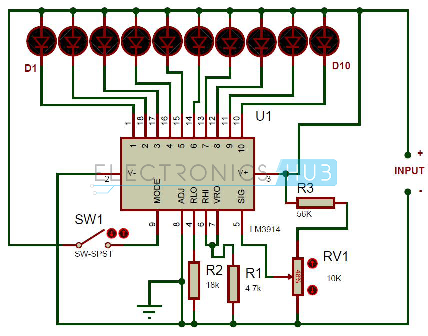
Battery Charge Indicator Circuit Design:
In this circuit LED’s (D1-D10) displays the capacity of the battery in either dot mode or display mode. This mode is selected by the external switch sw1 which is connected to 9th pin of IC. 6th and 7th pins of IC are connected to the ground through a resistor. This resistor controls the brightness of LED’s. Here resistor R3 and POT RV1 forms potential divider circuit. Here pot RV1 is used for calibration. There is no need of any external power supply to this circuit.
The circuit is designed to monitor 10V to 15V DC. The circuit will work even if the battery voltage is 3V. The operating voltage of this IC is 3v to 25v DC. Lm3914 drives led’s, LCDs and vacuum fluorescents. The IC contains adjustable reference and accurate 10-steps divider. This IC can also acts as sequencer.
Lm3914 Features:
- Internal voltage reference from 1.2 to 12v DC.
- Programmable output current 2mA to 30mA.
- LED driver outputs are current regulated.
- No multiplexing interaction between outputs.
- It supports wide range of temperature from 0 to 70 degree Celsius.
- For bar graph display – connect 9th pin of IC to the supply
- For dot display – leave the 9th pin of IC

No comments:
Post a Comment